Wardell Station welcomes you

Wardell Station welcomes you
Wardell Station late 1950s

Saturday 31 December 2016

Power on the Bridge

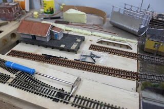
Work has commenced on developing a new area that will incorporate a 1970s section and fiddle yard. In order to for the trains to reach this new area a lift off bridge has to be built so that trains can go around the room and also that inside of the room can be accessed.

Test Run
Below is a test run of the CPH railmotor going over the lift off bridge with the safety zone in operation.


Safety Zone
In order to avoid any mishaps of locomotives still moving if the lift off bridge is up a safety zone is in place about 40 centimetres before this is an isolated section of track and only powered when the lift off bridge is down. A microswitch is installed near the hinge of the lift off bridge which triggers when power is made to the positive wires on the bridge


Wiring diagram
Sample wiring diagram found on the internet was used as the basis to complete the wiring for the safety zone and microswitch.
 Track Alignment
As the baseboard legs and shelving is movable a sawn connector rod and metal plug is use to align the bridge with the non-attached baseboard


Conclusion

I have been enjoying learning and doing the electronic side of building the layout. There is still some refinement and further testing to do but I am happy with the result

Happy New Year and until 2017


.

Monday 19 December 2016

Christmas 2016

Thanks for everyone's support during the year. Hope to have some new exciting development in 2017

Sunday 13 November 2016

Retrofitting lighting

After my post in August with the installed working street lights, I noticed that the platform and footbridge lacked any lighting. I decided that I needed to fit led lighting to both the platform light fittings and the footbridge. This took a bit of time and was quite difficult but I am happy with the results.
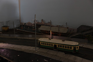
Above: Wardell station at dusk

Platform lighting
The platform light fittings are  Uneek double scroll top lights that are made of white metal and are solid with no actual light fitting. I purchase 10 warm white mini LEDS from a supplier in China from ebay and glued these to the top of the light fittings two for each light fitting. For Wardell station I used 8 LEDS two for each station lamp post.

Removal and reinstall
The most painful and tedious part was to dismantle my previous work such as the footbridge and station and platform. This is so that the I could drill holes in the baseboard to accommodate the lighting wiring to go the the AC power.

Footbridge lighting
The footbridge is quite a fragile structure and many parts had to be reglued. 
The other difficulty was installing lighting on the footbridge and footbridge stairs. I purchased a different set of LEDS for this.
The light fittings on  the footbridge were made from painted wire with plastic no stripped away.

Wiring for the footbridge and stair lights was also difficult as there was so many wires but limited space to hide them. I decided to use cut a terminal block into 2 ways so that all lighting wires would go into the terminal block and then only one set of lighting wiring would come from the footbridge to
the AC power .

Now that I finally finished the lighting I am looking forward to run some trains again!

Another view:Night Seen Wardell Station

Sunday 30 October 2016

On the Wire

Finally after several months of procrastinating and attempting to complete some of the finer details of the layout such as tram overhead wiring and the telephone poles, I finally completed it. My tramway system looks complete with overhead wiring.

Below is a photo of the screen looking on Crystal street bridge.


Technique for the telephone poles and wires
 The tram poles and telephone poles were a combination of bamboo sticks and Rix Products Railroad telephone poles.  I really like the Rix Products as the telephone poles are a taller than the Atlas branded ones. I also made some modifications so they would look more like the prototype in Sydney in the 1950s.


The telephone wires were made from 0.440mm gauge wire from Mitre 10.

Technique for the Tram overhead
I tried many attempts trying to use super glue to glue etched brass overhead fittings together to the wire without much success. The holes in the etched fittings were too small to put the brass wire through. I decided to do without the overhead fittings and just solder the wire together.  After my old soldering iron died I decided to purchase a new solder iron with temperature control and also a new helping hands.

This assisted the job quite a lot. Also by adding further frogs to the overhead for curves the structure became stronger.


Friday 16 September 2016

The end of the newsreel

"Good Evening and Welcome to Television"


Today is the 60th anniversary of when television was first broadcast in Sydney on 16 September  1956 by TCN Channel 9. Prior to this new technology, one had go to the local cinemas to see something on the screen .


The weekly newsreel provided patrons to weekly content of news, sport and current affairs that were shown at the local cinema. The onset of television resulted in the decline of the newsreel format as it could not keep up with bringing up-to-date news. It also resulted in the decline of the local cinema. 


Below is a tribute diorama to the anniversary. A newsreel film unit filming reviews of the new FE Holden Sedan in 1956.

The Holden FJ van is a Road Ragers diecast with custom designed and made decals. The film crew is a Preiser set.


 While the anniversary does not directly relate to my layout except that this event occurred in the 1950s it does allow me to display my other fetish. My HO scale model car collection. Here is a view of some of my collection as you can see my favourites are 1950s American cars.


Sunday 11 September 2016

Back to the boards

Lacking momentum
Over the last couple of months I have found it difficult to have the enthusiasm and momentum to complete the finer scenic details of the Wardell station section of layout. I would start a project such as installing the poles for the tramway wiring but did not have the patience to finish the frog and hanger wires.This was the same with the planned point rodding which has begun but not complete.

Back to woodwork

The idea of building the layout out was to build each module at a time before moving onto the next section i.e. trackwork, wiring and scenic section completed before moving onto the next board. Each module was either 600mm long or 1200mm long. This was to avoid the problem of biting off more than I can chew and also ensure that some scenery would be complete to do photo some model scenes.

Next Section
The next section of layout is loosely based on the goods area of Petersham before the Training Centre arose in its place. I am aware that there was a overhead wiring shed and a goods shed. However, I have no information of the goods shed as it slowly fell out of use before the 1950s.

Attached is a draft track plan of the next Section shaded in green and also the planned future section for part of the far wall.

Framework and backdrop
As shown with the timberwork to give some variety to the terrain there is some gradient for the main tracks to rise up gradually so that there will be a railway bridge. Whilst the tram tracks will gradient down so it will eventually be level with the baseboard. The area in between will be flat that represents the goods area.


 The backdrop is painted in Accent Iris Waters with a roller.

Here is a mock of the area with buildings. The G2 Goods Shed is taken from my Bilby Beach Layout which I feel has too big a footprint for the goods area. I might replace the The overhead wire Shed is represented by a Dunnyhalt plywood laser cut kit from Models and More. A kit that was easy to put together.


Trackwork has been laid down and using PVA glue and cork

Lasting thoughts:
I was pleased with the progress after two Sunday afternoons work. I still need to decide whether I should keep with the G2 Goods Shed or purchase a G1 Goods shed or another appropriate goods shed that would suit the area.

Thursday 18 August 2016

Leave the light on for Me

Its been a while since my last post, our yearly family vacation took some chuck of the time but I have found it difficult to focus in completing a couple of projects on the layout.


Lighting
The key thing that has been mostly completed is the street lights on the layout. I purchased some LEDs from Ebay and was able to glue them to the telegraph poles. I use a mixture of Two Dollar Shop satay sticks and Atlas Telegraph poles to build them.

To turn the lights on I installed a switch on the control panel next to the point switches.

Trafalgar street at dusk. Ready for the evening peak hour

Another shot with the station in the background
I was really happy to be able to complete this, that I showed my kids. Now everytime they come into the train room they like to turn the lights off and then switch the layout lights on.

After I had complete the street lights, I noticed that there were other lighting I needed to add to the layout and also vary some of the lighting so the brightness is not all the same. I hope to do this soon once I learn how I can change the brightness.

Saturday 21 May 2016

Return of the Red Rattlers

Four car red rattler set arrives at Wardell Station

 After a long absence updating this blog, I have finally been able to run some trains. The last time trains were running on the layout was about a year ago when the electronic controlled points and wiring were tested. So the track needed to be tested again and some of the wiring for the electronically controlled points and LEDs had come loose.

Once this was done, I was able to get some model trains running. I also added the catenary wire but discovered that the some of the stanchion posts needed to be re-positioned as the catenary wire was not centered in the middle of the track.

One of the first engines to test were my Sydney Suburban trains. Over the years I I had purchased two, two cars sets from Mini Models and a Suburban Parcel Van. The newer Bradfield  motor cars have working marker lights however the earlier sets did not working lights as well as the Parcel van. I intend to include these at a later stage. 

I have tested an added interior lights to the trailer car as shown in the photo. I interior to be able to connect this to a decoder so I can control when the lights can be turned off and on. There is a couple of stock to do so this may take time to do them all.

 Here is a Bergs Bradfield and Standard trailer 2 car set arriving at Wardell Station


Above: Another view of some of the suburban rolling stock a Suburban parcel van leaves Wardell Station for Central.

Above: View under the Crystal Street bridge looking towards Wardell Station

Wednesday 30 March 2016

And the Winner is?

The past month I have been able to complete more of the enjoyable part of building the layout. Building up the scenery including completing the station signage and building up ground cover, bushes and trees. 

Below is the completed station scene including overhead stanchions, catenary and station signage on platform signs and platform seats.


After much thought and research, I decided to name the station and layout, Wardell. Wardell, is named after Dr Robert Wardell, a barrister who became quite wealthy after he arrived from England and owned a large estate in the Petersham area in the 1820s. He was murdered by bushrangers on the boundary of his estate in 1834. His estate was subdivided upon his death1. Trafalgar street that is currently running parallel to Petersham station was previously called Wardell St.

Making Signs   
To do the signage I made my own decals using a computer and Publisher to do the lettering. This technique I used previously with my previous layout.
Testors has a Custom Decal System kit which includes decal bonder and decal paper in white and clear paper. The kit only includes 3 papers of each A5 sheets. I ran out of clear decal paper and could not source any Testors clear decal paper in Sydney. I found an alternative supply in Redfern. Below is a printout of the decals I had printed. To maximise the use of the decal paper, I think of all the decals I need for future projects which can fill up the decal paper. 


Once bonder is dry I cut out decals and apply to the platform seat and signs using warm water and Walthers decal solvent. The seats and signs I used were Uneek white metal detail kits from Anton Trains.  After the decal is set after a day I seal with Testors Dullcote.


Ground cover
I had a stash of foilage and scenery material from my previous layouts. However, most of it was dark green, I recently purchased a stack of lighter and medium green bushes, underbrush and coarse turf to complete what I had, to vary the scenery.

Using a mixture of what I already had and what I recently purchased I was able to provide a more realistic scenery scene for the area around the junction of Trafalgar St and Crystal st. Trees were reused from my previous layout Bilby Beach however I replaced the light green foilage with medium green foilage, The foilage used was from Heki which is like a coloured hair net that can be stretched.


 Above is the completed scenery of the ground cover and bushes.
1. http://dictionaryofsydney.org/entry/wardell_robert

Wednesday 2 March 2016

Catch the Subway

One distinguishing feature of Petersham Station is the pedestrian subway that connects Trafalgar and Terminus streets. It was built in1892 and originally had access to the platforms. The access to the platforms was closed after 1988 1. However, the subway still exists today to connect both streets.

Here is a photo of my completed model subway with a view towards "Petersham" Station. I have modelled this as it was before electrification took place. In the background is a 35 class loco waiting at the station.


Above: Photo of the prototype subway and Petersham station c1920 in which the completed model was based 2.
Construction techniques
Construction of the subway was based on the similar technique used for the Crystal St bridge which was described in a previous blog post, wood and readymade plaster cladded with Slaters weathered brick styrene. Since I had limited space, I did not used the measurements in the prototype but made the size to fit the space I had on the layout.
I used Faller Stairs and railing kit to complete the stairs. A mock hole is made to simulate the underground tunnel to reach the centre platform and exit at Terminus St.
Above: WIP of subway entrance
Subway Entrance today
During one of my fieldtrips to Petersham I was able to see the entrance of the subway which still has the brown bricks but is now surrounded by more trees and shrubbery. There is also a screen placed between the wall and the tracks so it is not possible to see the station from the subway entrance.
I believe the underground tunnel is covered in graffiti.


1. Petersham Railway Station Group NSW Environment & Heritage
2.  http://trove.nla.gov.au/work/10795197?q=petersham+station&c=picture&versionId=12603163

Thursday 4 February 2016

Inch by Inch - Foot by Foot

The latest addition to the layout has been the construction of a model of the footbridge which is based on the one located at Petersham station connecting Trafalgar Street and Terminal St. This has taken over 5 months in planning and build. It is 90% complete with a few additional parts to source and detailing to complete.

Above: Completed footbridge on "Petersham Station platform. Model is based on having the booking office still intact
Concept
One of the most prominent features of Petersham station is the footbridge. I sought to purchase something commercially available however the closest ones to the prototype were British kits. However, most kits connect from one platform to another but not from platform to street. In the end, I knew I had to build one from scratch using a number of different materials and parts.

Historical timeline, research and design
I found very good drawings including some coloured ones of the footbridge at the Heritage Resource Centre Redfern. 
This is the  timeline1 of the changes made to the footbridge. 
1884 - Built with latticework and cast iron columns with detailed ironwork under stairs
1896 - Footbridge widened with barrier fencing and 1st booking office installed on bridge
1926- Timber booking office installed on footbridge near Trafalgar st
Post 1970s - booking office and widened footbridge removed

Above: Left: Drawings of 1st booking office. Right: Drawings of changes made in 1926

Above: Drawings of original footbridge design. Scale is 3/16 inch to a foot.
 
The most challenging part based on these drawings was to convert the scale foot drawings from imperial to metric and then convert them into HO scale. Been born after inches and feet measurement were used meant that the drawings and its measurements did not make sense to me. I also needed to adjust the design to fit with my three width track layout and one platform compared to the actual prototype.

Booking Office
Although the booking office is no longer found on the footbridge. I found a photo in the late 1960s that showed it still existed at that time. Therefore, as I am modelling the 1950s it would of still been there. 
The very detailed drawings of two versions of the booking office had the advantage of making this part of the build the easiest. The walls were made from styrene clapboard and I used a technique of building windows and doors with scale lumber from one of the issues of Branchline. The difficult part I have found is scratch building the capped roof, to avoid previous failures I decided to experiment with cardboard to get the right angle before attempting on plastic molded tiled roofing. 


Build and detailed work
The concrete walkway of the footbridge was made from 3mm thick styrene. I could not source cast iron columns tall enough to represent those that hold up the footbridge. Instead, I used the drawings which showed that the booking hall was held up by a steel trestle. This was made from styrene and scale lumber.
To represent the latticework I had some Faller assorted fencing that I had from my childhood.

Above: The bridge takes shape

Almost there
The ornate footbridge railing was etched brass source from Scalelink in the UK which has some 1/87 scale railings and stair railings. The stairs were made from Faller Stairway kit and cut to length.


Above: Another view of footbridge viewed from "Trafalgar Street".
Above: View of Prototype