Wardell Station welcomes you

Wardell Station late 1950s
Thursday, 24 December 2015

Sunday, 22 November 2015
The First and the Last
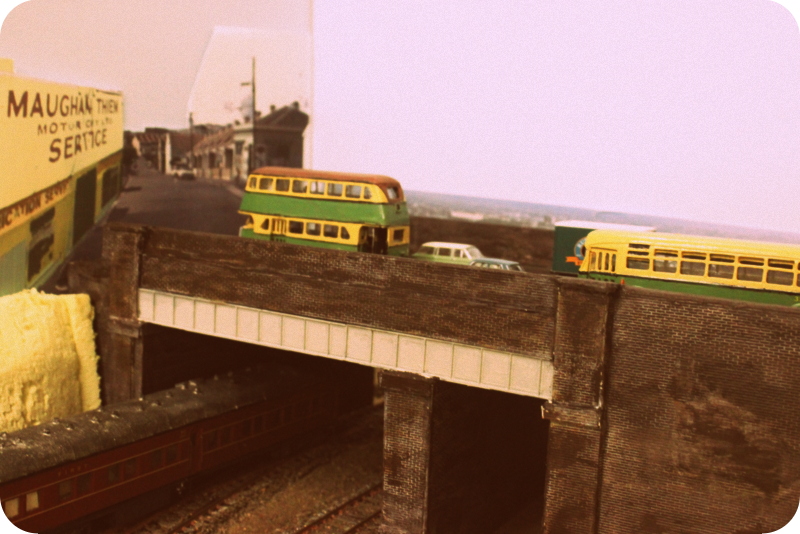
61 years ago today marks the day the last trams travelled along Crystal and Trafalgar St Petersham. The day was Sunday, the 21st November 1954 1. To mark this date, I have built my first Sydney tram, a R1 class white-metal kit by Weico, now no longer in production.
 |
| Above is the completed Sydney Tram R1 Class heading towards Balmain on Crystal St Road bridge. |
https://www.flickr.com/photos/74004041@N06/6971433185/in/photolist-efGmXu-6USmDw-bqpZPh-ea2i5G-bC3qcT-7kMQ3e-7HWpdM-dwCouv
Building the kit
I have found building White metal kits difficult at times. White metal needs strong glue. I use two part epoxy to do this but it takes 24 to 72 hours to dry so the parts need to be held together for a long time in order for the glue to cure. Also if the proportions are not correct it may also not cure correctly.
I made the kit per the instructions and then painted it in parts before gluing the whole thing together, i.e. the end drivers cabins painted separately from the main passenger section. I have temporarily used the trolley poles that came with the kit but will replace them later using ones that can be are operational. Although power will not come through the overhead wiring, the original trolley poles were not robust enough.
Painting
I had some green livery paint that I had when I built the Sydney Regal IV resin bus and used this for the green paint. I had a postcard of R1 1979 as a guide for painting. My cream paint that I previously used for the bus had already hardened so I had used Humbrol 74 plus a hit of matt white.
Interior was chocolate brown while the lower part of the body and bumper was the same acrylic brown I used for the road bridge without any mixture of black. I think it was dulux crimson russet.
To simulate the black painting lines on the tram body, I have used the technique of painting a thick black band on masking tape and then using a sharp knife to cut long thin lines. I then apply the masking tape on the tram.
I have found this method effective and used it on my previous bus models.

Motorising the tram
I purchased the motorised kit that was available by Weico for the R1 Class to run the tram. The motor is from Bowser Manufacturing. Wiring is simple with all both bogies having pick up. The kit came with one of the two of the universals not with the correct size and as a result broken part of that incorrect universal. I used gaffer tape to mend this. It did work but after a test run required more padding of the bolster to level the motor with the universals to have it straight so that the motor will run smoothly.
I purchased the motorised kit that was available by Weico for the R1 Class to run the tram. The motor is from Bowser Manufacturing. Wiring is simple with all both bogies having pick up. The kit came with one of the two of the universals not with the correct size and as a result broken part of that incorrect universal. I used gaffer tape to mend this. It did work but after a test run required more padding of the bolster to level the motor with the universals to have it straight so that the motor will run smoothly.
I also decided to paint the wiring and motor black to hid the fact that there was a motor in the tram body.
 |
| Above is the motor and bogies attached to the underfloor before painting the motor and wiring black. |
I wanted to have side panel period advertising on my tram. I sought old photos of trams from books and the internet to locate advertising on the side of trams, as those R1 class trams preserved do not have any advertising apart from the small advertising on front of the trams and used a computer and printer to make them.
With the decals, I found a website http://model-trams.com/model_tramway_accessories/ that does Sydney tramway decal numbers for trams. It appears that the decals are more catered for earlier trams that later numbered trams as there is not sufficient number of 9s in the decal sheet. I will likely need to get another sheet in order to do more R1 class trams.
What's next?
Whilst I have just completed my first tram kit, I still have a few more kits to build in the cupboard.
“This is what the Lord says—
Israel’s King and Redeemer, the Lord Almighty:
I am the first and I am the last;
apart from me there is no God"
Israel’s King and Redeemer, the Lord Almighty:
I am the first and I am the last;
apart from me there is no God"
Isaiah 44:6.
1. David R Keenan, The South-Western Lines of the Sydney Tramway System, Transit Press, 1992
Saturday, 31 October 2015
Back to 1955
This month on the 21st October marked, Back to the Future day, the day Marty Mcfly went to 2015. Being a avert Back to the Future fan I thought it would be appropriate to see how my layout would be set in 1955.

In 1955, the trams have long gone, buses have replaced trams at Trafalgar st, Petersham. The overhead wiring has disappeared and work is ongoing to asphalt over the tram tracks. Car traffic is slowly increasing with the reduced bus service.
Asphalt of Tramway commenced
As shown in the above photo, scenery work has commenced with the tramway work and footpath complete for some parts of the layout mainly the Crystal St bridge and the intersection of Trafalgar st, Petersham. There is still a large part of Trafalgar street that is still not fully complete.
The method I used for completing the tramway was using premixed plaster, Boral Total Joint Finish that came in a large plastic tub. I covered this on either side of the tracks and covered to the height of the sleepers. Although not my original idea, it was a recommendation from another tram modeller on TDU.

I then cut strips of Super fibre mesh cloth and laid this on before I put the second coat of premixed plaster to raise the level of the road to rail height.

When dry I sanded the plaster smooth and painted it matt black to represent asphalt.
For the area between the rails and between the two tracks I used 400 grit sandpaper that I previously used for my station platform and cut it to the appropriate radius and size.
Between the rails I tried to use 2mm styrene and then gluing the sandpaper on top of the styrene however I found that with the Hong Kong tram there was no sufficient clearance so I used the sandpaper without any additional thickness.
Between the two tracks I cut cardboard in appropriate widths and lengths and glued the sandpaper on it for
Footpaths and concrete roads
The footpaths were made from 3mm styrene thick with grooves cut every 1.5 cm to represent concrete slabs. These were then painted in concrete colour.
The concrete roads were made using Busch concrete plates which are printed cardboard sheets of weathered cardboard. These come in two sheet packs with four rows of concrete slabs per sheet. I used one row wide concrete slabs to represent the left hand lane of the road.
Here the Delorean heads back to 1985 after passing Biff's car which hit the manure truck.

Tuesday, 29 September 2015
Bringing back the cross-country connection
Work has started on building the tramway that ran down Crystal street and turned into Trafalgar street at Petersham. This was part of the cross country connection that serviced the Darling Street Wharf to Canterbury line.
Wiring
I decided to go DC for the tramway as the Weico trams which I have yet to built will only initially be DC. Futhermore, the Bachmann Hong Kong Tram which I use as a test vehicle is also only DC.
There are be two controllers one for each direction and have used block control using insulated rail joiners to allow independent running.
I have decided to make do with the controllers I have. I am using my old vintage controllers, a H&M Flyer and a Tyco/Kenbrite Train controller before I converted to DCC, This may change later if I decide to stay with DC or go with DCC.
Where the track merges into one, I have use a DPDT switch to power to the track between the two controllers. The track will split back into two further up the line where this has yet to be built.
 |
| Diagram of Tramway wiring |
Laying of track
Along Trafalgar St there was only one crossover, however I have installed two on the layout as the tracks merge into two at the far end of the layout. The track was laid using track pins and PECO code 100 flexible track was used. For the crossovers, PECO radius no: 2 insulfrog points were used.
.
 |
| View of Crossover near Petersham Station |
Although I have since learnt that most advanced modellers frequently do not use Code 100 I had a stash of unused radius no: 2 insulfrog points that were Code 100 and also too tight for my locos to use. I thought I would use the points here so these would not go to waste.

| View looking West along Trafalgar St |
Future work
There is still much work to finish off the tramway including paving of the road, installing overhead wiring and general scenery. Hope this would be complete in the next blog update.
Tuesday, 25 August 2015
Road bridge on Crystal Street
Its has been a while since my last post, busy family life with our annual family holiday in July and sickness in the family in August meant that the layout had taken low priority.
Dimensions
In my last post, I had started construction of the road bridge on my layout that would go over the main line. The bridge is roughly based on the Crystal Street road bridge in Petersham and I was fortunate enough to be able to obtain a copy of the drawings of the dimensions from the ARHS Research Centre. The drawing was dated from 1931 and gave me an indication of how tall and wide the structure should be. As my layout only has two tracks the length of the bridge will be modified.
 |
| These drawings pre-date the additional track and support made on the north side of the bridge. |
Materials used
- Scrap plywood
- Thick cardboard and foamboard
- Atlas N scale girder plate kit x 2.
- Slaters 00 scale Plastikard English bond x 3
- Wall Plaster
Using the drawings I was able to cut the plywood to the desired height and length to represent the supports and the road base. Where brickwork butted out I used foamboard and thick cardboard to represent this. I was happy with how strong the bridge would be considering it would need to be solid enough to hold the tramway. I decided to clad, paint and weather both sides of the bridge although at present only on side is shown in view on the layout. However, later if this changes it provides the opportunity that I will not need to model the other side of the bridge later.

The girder plate was made by gluing two lengths of the Atlas N scale girder plate together and then
cutting it to the appropriate length.
Finally, I found it difficult to find a suitable material to represent the brickwork. I tried using a variety of Superquick brickpaper & Paperbrick online but I was not happy with the colour and lack of texture.
Also, whilst I did purchase Noch Brick sheets I found that the bricks were too big. In the end, I settled for Slaters 00 scale Plastikard English board to clad the structure.

Finally, after cladding the structure with the brick sheets I found gaps where the sheets met each other and used plaster to cover the joins. Furthermore, I used the plaster to provide a smooth finish for the top of the brickwork.
To achieve the brick colour, I used Dulux Rusted Crimson mixed with black and weathered it with a variety of acrylic browns, white for mortar as well as concrete colour. While 90% of the work is done, the bridge still requires tram tracks, painting of road base and footpath to be install to complete the picture.

Sunday, 14 June 2015
The little tram that could
Scenery work starts
Since the last post various pieces of work have commenced:
Prior to the advent of the popularity of the motor car in the 1950s, roads were shared by trams and other forms of traffic such as horses and wagons. Cars became more popular after World War II when the Australian economy was booming and families could afford to purchase a motor car. This spelt the end of Sydney's extensive tram network.
For my layout, I wanted to include trams having experience living in a city with trams in Basel, Switzerland and also as Sydney was my place of birth, I also was intrigued that trams use to run along some of the places I knew of in Sydney.
Petersham was the location of choice as a tramline co-existed with train line adjacent to it.
Since the last post various pieces of work have commenced:
- Construction of the Crystal Street road bridge which will be described in a later post after I obtain the necessary modelling supplies to complete it
- Creating the backdrop using photos which will also be described in a later post
- And finally the construction of the tramway running parallel to "Petersham" station (a name has yet to be decided on the station name)
Prior to the advent of the popularity of the motor car in the 1950s, roads were shared by trams and other forms of traffic such as horses and wagons. Cars became more popular after World War II when the Australian economy was booming and families could afford to purchase a motor car. This spelt the end of Sydney's extensive tram network.
For my layout, I wanted to include trams having experience living in a city with trams in Basel, Switzerland and also as Sydney was my place of birth, I also was intrigued that trams use to run along some of the places I knew of in Sydney.
Petersham was the location of choice as a tramline co-existed with train line adjacent to it.
 | ||
| Sydney R1 Tram heading west on Trafagar street before tuning into Audley Street Image source: http://tdu.to/14749.att Noel Reed 20.11.1954
Making the tramway work
The tramway/road uses the same 7mm thick plywood as the base of the train track to ensure the tram tracks had a good strong foundation. I used scrap bits of plywood as height incliners with liquid nails and nail to hold the framework together.
The little tram that could
The main challenge was to get the right incline of the road. The road needed to go up to a height of 110mm (the height of the Crystal St road bridge) and I wanted it to reach this height at the shortest length as possible. I initially intended to do this within a 1 metre length.
However, having tested this with a Bachmann Hong Kong tram with a 10% grade, it was discovered that this was not going to work.
I decided to not be so ambitious and ended up with a 1 to 3.75 incline or 3.33% grade for my test tram.
|

Monday, 11 May 2015
What's in a name?
Since the last blog post, I have completed more of the scenery on my layout. However, there are still two large structures yet to complete and as yet the layout and station still does not have a name.
Asphalted platform
I wanted to simulate an asphalted platform using wet and dry sandpaper. Bunnings had rolls but the width was too narrow. I found a supplier on the Internet "Mr Sandpaper"who was able to supply my needs I was able to purchase a large 2 metre roll that was about 30 cm in width so I have enough to use this surplus for later use.
Platform length and platform furniture
The platform has been completing using the AMRI platform and peco ramps as the basis. The platform in whole is about a metre long so it can handle a four car set. Platform furniture such as seats and indicator boards are painted in period colours of the 1950s supplied by Anton Trains Uneek. I only bought 1 set of platform seats (3 in a pack) but I will require at least 3 more packs.
I will probably need to see what other items I need to add to give my station some more life.
I have also added the subway steps that were located in the western end of the platform that has since been covered up.
Backdrop
My idea was to have the old style Victorian Italianate Petersham station as the backdrop so I would not need to model the complicated architecture. Also for the period I was modelling (the 1950s) the station was no longer used.
I used photoshop to stitch two photos together and then used Office works printing to print the colour photo on a large A2 paper. I then cut the photo and glued it on foamboard.
I am happy with the effect but I believe I need a period skyline to provide more fill between the sky and the building.
Layout and Station name
Although the station area is based on Petersham station it will not follow the track layout and structures exactly to the prototype. Therefore, I was thinking of an alternative name for my layout and station name.
Searching the internet I discovered some interesting history of the Petersham area and some ideas of names come up. As yet I a name has not been confirmed.
Some suggested names I thought of:
 |
| Above: My station loosely based on Petersham station. A "newly" built 42 Class loco coming through. Station name has yet to be decided. |
Asphalted platform
I wanted to simulate an asphalted platform using wet and dry sandpaper. Bunnings had rolls but the width was too narrow. I found a supplier on the Internet "Mr Sandpaper"who was able to supply my needs I was able to purchase a large 2 metre roll that was about 30 cm in width so I have enough to use this surplus for later use.
Platform length and platform furniture
The platform has been completing using the AMRI platform and peco ramps as the basis. The platform in whole is about a metre long so it can handle a four car set. Platform furniture such as seats and indicator boards are painted in period colours of the 1950s supplied by Anton Trains Uneek. I only bought 1 set of platform seats (3 in a pack) but I will require at least 3 more packs.
I will probably need to see what other items I need to add to give my station some more life.
I have also added the subway steps that were located in the western end of the platform that has since been covered up.
Backdrop
My idea was to have the old style Victorian Italianate Petersham station as the backdrop so I would not need to model the complicated architecture. Also for the period I was modelling (the 1950s) the station was no longer used.
I used photoshop to stitch two photos together and then used Office works printing to print the colour photo on a large A2 paper. I then cut the photo and glued it on foamboard.
I am happy with the effect but I believe I need a period skyline to provide more fill between the sky and the building.
Layout and Station name
Although the station area is based on Petersham station it will not follow the track layout and structures exactly to the prototype. Therefore, I was thinking of an alternative name for my layout and station name.
Searching the internet I discovered some interesting history of the Petersham area and some ideas of names come up. As yet I a name has not been confirmed.
Some suggested names I thought of:
- Sydenham farm - Prior to the current station been named Petersham it was called Sydenham as this was the name of the part of the estate.
- Wardell - A wealthy barrister own large parts of Petersham before it was subdivided he was shot by criminals trying to rob his estate.
- South Kingston or just Kingston - This was the name of the Ward that covered the station area of Petersham. It was named after it was part of an estate.
- Toot-hill - This was an area used for deer hunting. A street in Lewisham has been named after it
- Newsham - A hybrid of Petersham and Newtown stations
- Stansham - a hybrid of Petersham and Stanmore stations
Wednesday, 1 April 2015
The Colour of Bricks?
The last 4 weeks I have started building the platform and the main station based on the Petersham Station. Most of the time has been spent trying to work out the correct paint colours to represent the brickwork on my station using the AMRI NSW A9 Station kit as the basis with very little modifications.
First Attempt
With the aim of minimising the use of enamel paints I sought to use acrylics wherever possible.
 |
| Kit out of the box with first attempt of painting mortar with Tamiya flat white. The original plastic red was initially going to be used as the brick colour |
Ideas for brick colour
After my annual visit to the Forestville Model Railway Show in Sydney,I decided that I had found an example of the colour of the brickwork that I wanted. Discussions with the representative of the Brunswick Park layout provided me useful information that grime coloured paint was airbrushed on the station building.
 |
| Suburban Station on Brunswick Park Layout. |
Trial and Error
Without getting my airbrush out I made several attempts and experimenting with dry brushing and using Floqui grime as mortar and a mixture of Tamiya browns paints to get the right brick colour.I was quite happy with the weather-look that took away the plastic finish. Although not the same colour as the brickwork seen in the station on Brunswick park I thought it was close.
Most of the brick work colour was Tamiya Hull Red with lighter browns underneath such as dark brown and earth. Gables and window frames were painted in Humbrol Oak. After painting was completed I set about building the kit. This was the most enjoyable part of doing the model as I felt it was back to basics and building a plastic kit again. The only

Let there be light
With my previous layout having building lit on the layout I also thought that having lights for the station would also provide a great effect considering it will be a prominent building on the layout.
I used 3 volt grain of wheat incandescent light bulb. Three on each side for lighting under the awning and one bulb to light up the interior.
 |
| Station which 95% complete with lighting. |
I am pretty much happy with the building this station there are a few minor details to complete but hopefully it will be ready for passengers to use on my layout shortly.
Sunday, 1 February 2015
One year on.....
Time flies!
Its now been one year since I had have the new train room to build my dream layout. If this was a task that I had to complete at work with budgets and goals set I would have failed miserably in missing them. At the beginning of last year, I would have thought that by Christmas time, I would have some of the dream layout built and operating whilst chatting with friends over a beer around the layout.
The reality is that the first quarter of last year was cleaning out the room, six months was spent building the benchwork and the last quarter was spent doing trackwork and electricals for one module of the planned layout. Its been hard at times but I have honed my carpentry and electrical skills both of which are my least favourite activities in building a layout.
The fun begins
There is still alot of work to do. However, the good news is that in the last few weeks I have been able to commence the detailed scenery work for the Petersham module of the layout. I have starting to plan building some structures with the signal box and station which for me is the most enjoying part of hobby.
Ballasting (to non-trainheads adding rocks under the railway sleepers).
To simulate ballasting, I have used track pins to nail down the Peco code 70 flexitrack onto AMRI cork and then using diluted white glue to apply the model ballast with an eye dropper. I had previously used Chuck's Ballast Martins Creek fine on my previous layout and had 1/2 kilo left. So the easiest decision was to use the remaining supply I had the purchased another kilo and to complete the rest of the module.
I looked at other colours made by Chuck Ballast at the model store but I felt that the other colours were too brown. I am not sure what colour the ballast was used within the Sydney region and I have used my modellers licence to decide this colour rather than try to match the prototype.
Weathering the track and wooden sleepers
I thought I would try and glue the Ballast first before painting the side of the rails with rust colour and then painting the wooden sleepers with enamel grey colours I had in my paint box (Humbrol sea grey 27) and then Humbrol 147 Light grey over it.
This worked as long as the ballast was not loose. In hindsight it is probably easier to weather the sleepers and rail first before ballasting.
It is intended that I then will use some of the Rustall blackwash and deadflat to give the wooden sleepers a stressed look.
Mid Year goals
Whilst I don't want to jinx myself in not being able to meet some goals I thought it would be good to at least set some goals to see if they could be achievable by mid this year and only limit this to the Petersham module.
* Complete Petersham station and platform, kitbash signal box, footbridge and Crystal street bridge.
* Add lighting to the above buildings
* Add Victorian Petersham station building in backdrop.
* Complete ground cover in goods yard.
* Start work on Trafalgar street and tramway.
Before and after shots 1 year later
Its now been one year since I had have the new train room to build my dream layout. If this was a task that I had to complete at work with budgets and goals set I would have failed miserably in missing them. At the beginning of last year, I would have thought that by Christmas time, I would have some of the dream layout built and operating whilst chatting with friends over a beer around the layout.
The reality is that the first quarter of last year was cleaning out the room, six months was spent building the benchwork and the last quarter was spent doing trackwork and electricals for one module of the planned layout. Its been hard at times but I have honed my carpentry and electrical skills both of which are my least favourite activities in building a layout.
The fun begins
There is still alot of work to do. However, the good news is that in the last few weeks I have been able to commence the detailed scenery work for the Petersham module of the layout. I have starting to plan building some structures with the signal box and station which for me is the most enjoying part of hobby.
Ballasting (to non-trainheads adding rocks under the railway sleepers).
To simulate ballasting, I have used track pins to nail down the Peco code 70 flexitrack onto AMRI cork and then using diluted white glue to apply the model ballast with an eye dropper. I had previously used Chuck's Ballast Martins Creek fine on my previous layout and had 1/2 kilo left. So the easiest decision was to use the remaining supply I had the purchased another kilo and to complete the rest of the module.
I looked at other colours made by Chuck Ballast at the model store but I felt that the other colours were too brown. I am not sure what colour the ballast was used within the Sydney region and I have used my modellers licence to decide this colour rather than try to match the prototype.
 |
| Above: Start of the ballast work in the proposed Petersham goods yard area with the fibro signal box. I have kitbashed and added a brick foundation but still not happy with it as there is additional work required to make it look like the Petersham prototype. |
Weathering the track and wooden sleepers
I thought I would try and glue the Ballast first before painting the side of the rails with rust colour and then painting the wooden sleepers with enamel grey colours I had in my paint box (Humbrol sea grey 27) and then Humbrol 147 Light grey over it.
This worked as long as the ballast was not loose. In hindsight it is probably easier to weather the sleepers and rail first before ballasting.
It is intended that I then will use some of the Rustall blackwash and deadflat to give the wooden sleepers a stressed look.
Mid Year goals
Whilst I don't want to jinx myself in not being able to meet some goals I thought it would be good to at least set some goals to see if they could be achievable by mid this year and only limit this to the Petersham module.
* Complete Petersham station and platform, kitbash signal box, footbridge and Crystal street bridge.
* Add lighting to the above buildings
* Add Victorian Petersham station building in backdrop.
* Complete ground cover in goods yard.
* Start work on Trafalgar street and tramway.
Before and after shots 1 year later
 |
| Last year: Before new layout commenced. Old Bilby beach layout in background |
 |
| Now: Same view of room with Petersham module complete with benchwork, trackwork and electrical work. |
Wednesday, 7 January 2015
With a Little Help From My Friends
First of all, a Happy New Year to my regular blog readers.

Turnout Indicator lights
Another challenge was that I wanted to incorporate a control panel which includes LED lights for turnout indicators. The idea was that if I used a toggle switch to motorise the turnout it will also indicator the direction of the turnout: Red for turning and green for straight.
Not knowing where to start I found the following indicator light information on the Internet as a basis for wiring the LED lights.

By only using this diagram and after soldering 5 green and 5 red LEDS as well as the 1K resistors I found that some of the LEDS were always on or always off. I was stumped as to why they were not working.
With a Little Help From My Friends
Two of the people who viewed the layout over the holiday period such as my brother-in-law (who I didn't know was trained as a electrician) were electrically minded.
They viewed the wiring and were a great help in diagnosing where the problem may lie.
They also provided some useful hints and advice:
* A short tuition on how to use basic functions of a the multimeter (although I had one I didn't know how to use it)
* Determine whether current was flowing through the wires using the multimeter
* LEDs have a positive and negative legs so having determined this I found out that my wiring were incorrect for some of the LEDS and I had to undo and redo some of the LEDS.
* Test the LED lights before soldering using the multimeter
* Teach me how to make the wiring more neater and organised
If I feel up to it I may create a circuit diagram of the electronics for the first module.

The past 6 weeks have been busy finishing off the electronics on the first module. We had family and friends at Christmas and New Year and I wanted to show the layout with something that was operational.
Polarity changes
As written in the last post, I was able to get the Peco turnout motors wired and working correctly. However, as the turnouts are electrofrog it will need to also include a switch to change the polarity of the turnout so that the track does not short circuit.
I used the Peco PL-13 Accessory Switch to change the polarity and followed the instructions as per below. The instructions were not clear as to which wires (positive or negative) to connect to each of the rails I assumed that depending on whether it was a left or right hand turnout it could be either positive or negative.
Turnout Indicator lights
Another challenge was that I wanted to incorporate a control panel which includes LED lights for turnout indicators. The idea was that if I used a toggle switch to motorise the turnout it will also indicator the direction of the turnout: Red for turning and green for straight.
Not knowing where to start I found the following indicator light information on the Internet as a basis for wiring the LED lights.
By only using this diagram and after soldering 5 green and 5 red LEDS as well as the 1K resistors I found that some of the LEDS were always on or always off. I was stumped as to why they were not working.
With a Little Help From My Friends
Two of the people who viewed the layout over the holiday period such as my brother-in-law (who I didn't know was trained as a electrician) were electrically minded.
They viewed the wiring and were a great help in diagnosing where the problem may lie.
They also provided some useful hints and advice:
* A short tuition on how to use basic functions of a the multimeter (although I had one I didn't know how to use it)
* Determine whether current was flowing through the wires using the multimeter
* LEDs have a positive and negative legs so having determined this I found out that my wiring were incorrect for some of the LEDS and I had to undo and redo some of the LEDS.
* Test the LED lights before soldering using the multimeter
* Teach me how to make the wiring more neater and organised
If I feel up to it I may create a circuit diagram of the electronics for the first module.
The End Result
After correcting the LED wiring I found out that still some of the LEDs didn't work.
I rechecked all the LEDs again and then revisited the wiring of the Peco instructions of the PL-13 switch above and decided to remove the two wires that connect the track to the two connectors that were close together. I also ensured that the PL-13 switch was connected to negative rail and also ensure that the connector shown in the indicator diagram was connected to the track with a negative as per the turnout indicator diagram
Finally, Presto it worked below is the video showing the workings of the indicator lights and turnout motors.
Subscribe to:
Posts
(
Atom
)